Multifunction Instrumentation System
A Raspberry Pi-based digital multimeter and function generator featuring custom analog front-ends, a software-driven SAR ADC, and a 4-layer mixed-signal PCB.
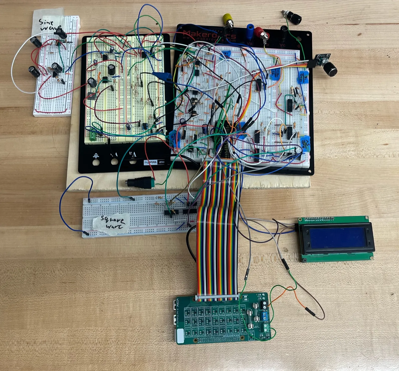
Highlights
- Built a Raspberry Pi digital multimeter and function generator in Python with a ±12 V split-rail supply and active virtual ground
- Designed a SAR ADC from a digital potentiometer and comparator for a ±5 V voltmeter, 500-10 kΩ ohmmeter, and ±5 V reference
- Implemented function generators (0-10 Vpk, 0-10 kHz) and a 0-10 kHz frequency counter with op-amp conditioning
- Improved DC resolution ~6x and voltmeter precision ~2x by adding digipot calibration LUTs
- Designed a 4-layer mixed-signal Pi HAT PCB in KiCad with dedicated power and ground planes
Overview
ECSE 2920 course project with a five-person team. I designed and built the measurement and generation path end to end — Pi software, analog front-ends, digipot SAR ADC, and calibration — while teammates handled the enclosure, wiring documentation, and demo slides. The M.I.S. folds a bench of lab instruments into one platform. The Raspberry Pi 4 is the only processor: Python firmware runs the measurement algorithms, waveform output, and a menu-driven interface on a 20×4 I²C LCD with a rotary encoder. Custom analog circuits handle signal conditioning, comparison, and generation.
Results
| Instrument | Range | Accuracy |
|---|---|---|
| Ohmmeter | 500 Ω – 10 kΩ | ±10% |
| Voltmeter | −5 V to +5 V | ±0.2 V |
| DC reference | −5 V to +5 V, 32 levels | ±0.2 V |
| Square-wave generator | 100 Hz – 10 kHz, up to ±10 V | ±1 V amplitude |
| Sine-wave generator | 1 – 10 kHz, 0 – 10 V peak | ±0.2 V amplitude |
| Frequency meter | 1 – 10 kHz | ±2% |
Those 6× / 2× gains come from characterizing the digipot’s real resistance steps and replacing naïve wiper-index math with calibrated lookup tables (plus interpolation on the voltmeter). Split-rail bring-up measured −12.04 V / +12.05 V under load.
Measuring with a comparator and a digipot
The Pi has no ADC, so the voltmeter and ohmmeter use a discrete successive-approximation converter. An MCP4131 digital potentiometer sets a reference over SPI, an LM339 comparator reports whether the input is above or below it, and the firmware binary-searches the wiper in 8 steps, which takes about 40 ms per reading including settling time.
- Ohmmeter: the unknown resistor forms a divider against the digipot, and the converged wiper step gives
R = R_known × step / (128 − step). A 1 kΩ series resistor keeps the wiper current under the MCP4131’s 2.5 mA limit even at 500 Ω. - Voltmeter: summing and inverting amplifiers map −5…+5 V into the 0–3.3 V comparator range, and a calibrated lookup table with linear interpolation brings readings to ±0.2 V.
Generating signals
Click bits on the interactive R-2R ladder below — the ladder stays at 0–3.3 V; the op-amps map that to −5…+5 V.
- DC reference: five GPIO pins drive an R-2R ladder (0–3.3 V), a non-inverting stage scales to 0–10 V, and a difference amp subtracts 5 V for a bipolar −5…+5 V output. An earlier binary-weighted design suffered from cross-loading between bits; the R-2R ladder presents a constant impedance and stays monotonic across all 32 codes.
- Square wave: the Pi’s hardware PWM is RC-filtered, then an MCP4231 dual digipot sets amplitude and offset ahead of a gain-of-10 difference amplifier, giving a 0 V-centered output up to ±10 V.
- Sine wave: the Pi’s audio output is buffered, offset, and scaled, with an MCP4131 providing digital amplitude control up to 10 V peak.
Timing on a non-real-time OS
Linux scheduling jitter rules out bit-banged timing in Python. The frequency meter squares up the input with a comparator, and the pigpio daemon timestamps each rising edge with microsecond resolution in the background. The UI loop computes frequency from a rolling 100-period buffer and rejects outliers beyond 2σ, so measurements never block the interface. Leaving a menu automatically disables waveform and DC outputs as a safety interlock.
Power and PCB
A ±12 V split rail comes from a single 24 V input: a TL081 buffer drives an IRFZ34N / IRF5305 push-pull stage that holds a virtual ground at the midpoint, tied to the Pi’s ground at a single star point. With both rails loaded they measured −12.04 V and +12.05 V.
The whole system is captured as a hierarchical KiCad schematic and a 4-layer Pi HAT layout with dedicated power and ground planes, with DRC-checked Gerbers ready for fabrication.
Demo videos
Interactive DC reference
Five GPIO bits drive an R-2R ladder (0–3.3 V). A non-inverting stage scales that to 0–10 V, then a difference amp subtracts 5 V for a bipolar −5…+5 V output.
R-2R → gain / offset
Click a bit on the ladder, scrub the code, or sweep all 32 levels. The ladder stays in the Pi’s 0–3.3 V domain; the op-amps do the bipolar mapping.
- Code
- —
- Binary
- —
- V_R2R
- —
- Vout
- —